Controls 2
Controls 2
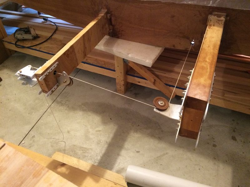
Below, you see one of the two extra pulley-and-bracket compononents that I designed and mounted to the front of the rear spars to ensure good alignment for the cable as it passes through the rear spar to the aileron bell crank.
Notice, also, how I cranked the front pulley mounting bracket upwards about 10 degrees so the cable would travel up cleanly from the front spar pulley to the rear spar pulley. Since my front spar pulley brackets are of greater length than the plans design and I had to beat them with a rubber mallet to bend them, I decided to use thicker aluminum for them.
In the plans wing profile (RAF 48), the cable passes straight from the front pulley to the aileron bell crank. No doubt someone has come up with a better solution than mine to this issue, which is created by the different side-profile of the AS 5048 center spars. It seems like more than a few people are using rigid push-rods for controls these days, but I simply never considered using them. Probably worth looking into when you build your KR. The two extra pulleys cost me an extra $50 total and obviously add a little weight to the control system. At any rate, I feel good that everything is attached cleanly and at straight angles.
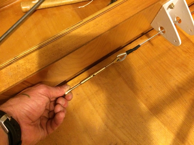
I've finally purchased all my "real" control components, including turnbuckles like the one pictured above, shackles and control cables. These particular pieces of AN hardware are expensive!
I'm fabricating all the aileron control elements at this point, getting the cables to the proper lengths. I was happy with the smooth operation of the controls. Once the stub wings are complete, I'll reinstall the cables, and use the turnbuckles to tighten everything up to the proper tension.
I used the "nico-press" system to create the loops in the cables--an easy and effective swaging method.

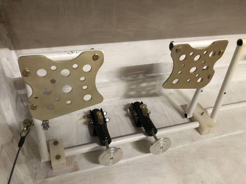
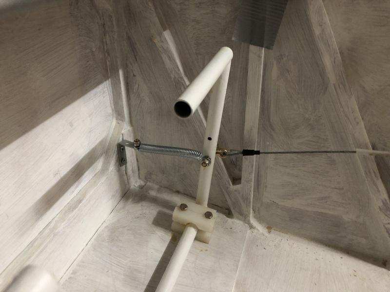
Above (Sept. 2023): After trying many different attach points with my original elevator control configuration, I could not get the elevator to travel the required 30 degrees up and 20 down. The pushrod from the control stick originally passed under the rear spar. Some mechanical realities with that setup slowly dawned on me. To fix it, I opted to make the pushrod pass over the spar, necessitating a new position for the rear spar crank.
The elevator cables now have to cross each other as they pass back through the rear fuselage to the elevator. I had to reinstall a pulley on the front post of the vertical fin as a result (see "Tail 2"). As you can see from the picture, I still had to attach the pushrod almost a full inch closer to the rotation point of the rear spar crank in order to get the required travel. In the end, the elevator works great, and the feel of the stick is smooth and not too heavy, despite the smaller rotation radius at the rear spar crank.
Above: Having the elevator pushrod go over the rear spar has some ramifications for the cockpit interior. I was planning to put an elbow rest right there; the rod will pass through it.
Above (Oct. 25, 2023): Heel brakes installed.
Above (October 25, 2023): Rudder return springs installed. The other way to do this is link the outside rudder pedals by a cable through pulleys attached to the firewall. This setup seems to work well though.