Landing Gear
Landing Gear
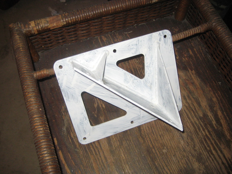
Since my AS 5048-45 spars are taller than stock, I designed landing gear brackets, below, to fit them. These are made of 1/8" thick 4130 steel, laser-cut and welded by a local machine shop. All my steel components have been sandblasted, etched with a metal etcher, and covered with epoxy primer. I'll cover them with a nice topcoat of paint later.
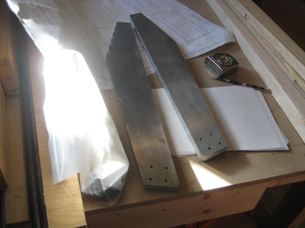
Above are the landing gear legs. I bought a 3/4" thick hunk of 7075-T6 aluminum and gave it to my local machine shop with some cad plans, and they cut these out with a water jet. They're 27 inches long and fit perfectly into the brackets above. They'll protrude at a 45 degree angle to the sides, and about 18 degrees forward from the spars (I'm building a taildragger).
All my aluminum components will be shined up, deburred, etched with Alumiprep, painted with Alodine, and then covered with a good primer.
I'll make fiberglass fairings for the legs to make them more aerodynamic.
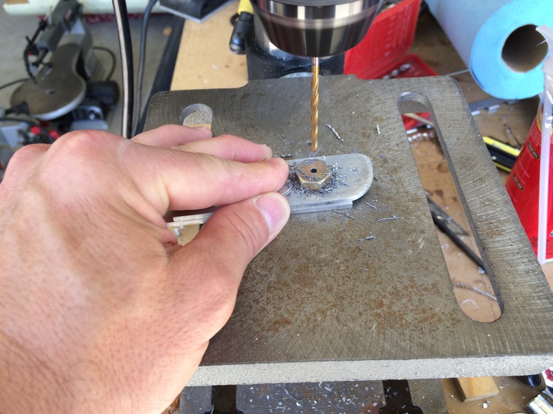
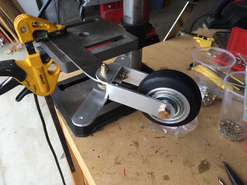
Above: The plans call for a homemade tailwheel installation. I figured "why not give it a try." Here I am drilling a hole through the head of a 3/8" bolt, two of which will serve as bearings through which the pivot bolt of the installation (a 3/16" bolt) will pass. If you keep your drill press at a low speed and let things cool down regularly, it's really not that hard an operation. I did not break any drill bits. Securing the bolt to a scrap piece of aluminum with a nut was a good idea, to keep the bolt perfectly vertical while drilling. I got two perfect holes in four tries.
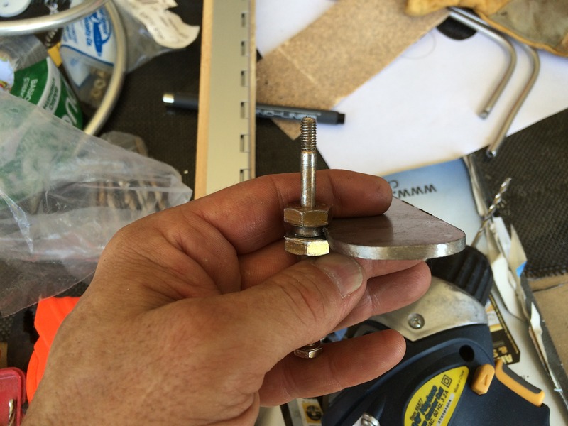
Above, I'm holding the two drilled bolt heads next to the 1/8" thick steel tailwheel arm. Based on my interpretation of the somewhat unclear plans, I cut one of the 3/8" bolt heads clean off from its shaft, whereas I left 1/8" of the other shaft to protrude through a 3/8" hole in the tailwheel arm. I'm not going to attach these "bearings" to the arm, but will let everything rotate freely. It will remain to be seen where the most friction takes place...
Above, things turned out really well--the tailwheel bracket swivels freely and smoothly around the 3/16" pivot bolt. The plans were right on except for one thing: I had to use an extra, thin washer to help everything fit tightly within the bracket. It's a light and inexpensive installation. We'll see how it holds up. The tailwheel is $25 from Wicks.
.jpg)
Above: with the bottoms of both stub wings glassed, and with the plane still on its back, it was time to install the landing gear legs. I cut out the smallest holes possible directly above the landing gear brackets to insert the legs. I will save the cut-out panels. When the time comes, I will shave the cut-outs as necessary and glass them back in as close-fitting patches.
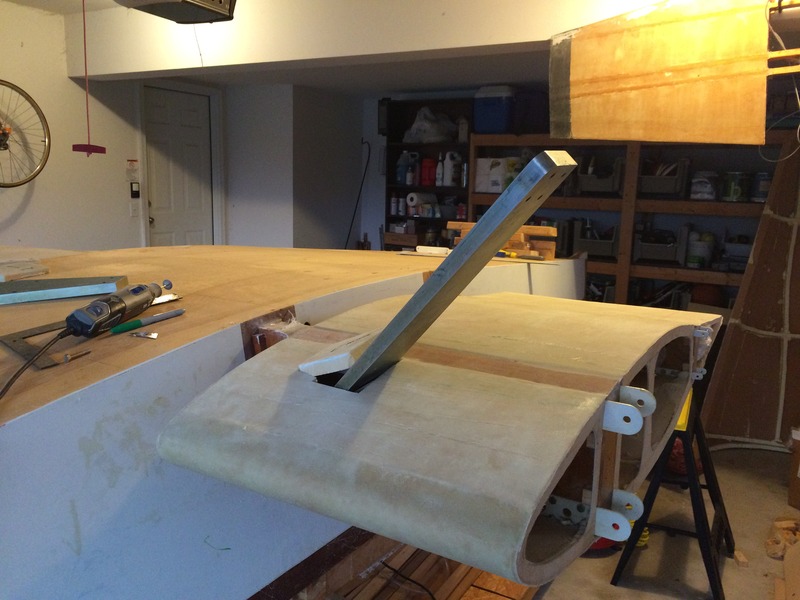
It was pretty difficult bolting the legs onto the brackets with so little room to maneuver. I finally succeeded by spraying the tip of one finger with adhesive for washers and nuts, and sticking one hand through the leg hole and the other through the side of the stub wing. Before bolting them in, I shined the legs up real nicely and used Alumiprep on them, followed by epoxy primer. One of the last jobs of my build will be to make the landing gear legs more aerodynamic with foam and fiberglass fairings on the leading and trailing edges.