Seat
Seat
The first few steps of both my seat and "bellyboard" (air-brake) installations happened together.
For the air-brake, I've followed Mark Jones' approach.
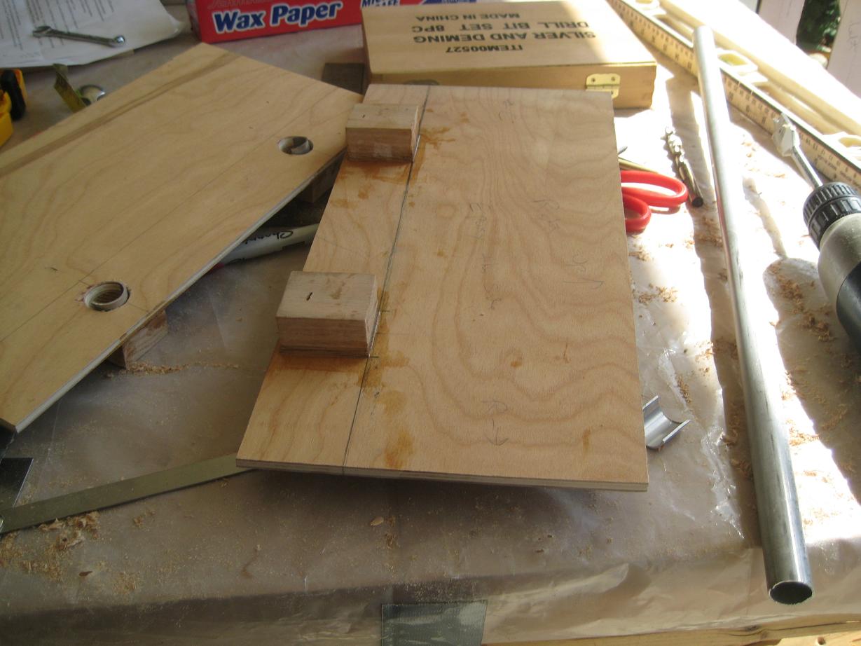
Below you can see two 1/4" thick birch ply panels. The panels will drop from the forward face of the rear spar to the floor of the fuselage, providing a strong structure to which the airbrake can attach.
To the panels' back faces, I've epoxied four 2" by 2" oak blocks. I would not feel secure using spruce to do this job. Each of these blocks weighed exactly two ounces after I drilled them out. There are eight blocks in all, totaling one pound. If this approach does not turn out well, I'll have a half-pound of oak in my plane which I will never be able to get out.
The oak blocks are positioned on the 1/4" ply so that when the plywood is mounted to the front face of the rear spar, the blocks will tuck up perfectly against the underside of the spar, to which they will be epoxied. They do not touch the weak fuselage floor.
Through the ply face and into the oak blocks, I've drilled 7/8" holes at 20 degree angles, into which the seat support tubes will fit. I cranked the drill upwards at the end of the drilling process to make the holes slightly oversize, but only on top. This allows you to tilt the seat support tubes upward to remove them. I left a 1/2" thick wall of oak at the back of all the holes. Then I poured T-88 and flox into the holes to form a durable plug, about 1/4" thick. The aluminum semi-circular tabs will be floxed into the holes. They have an inner diameter of 3/4" so that the seat support tubes will nestle in them snugly.
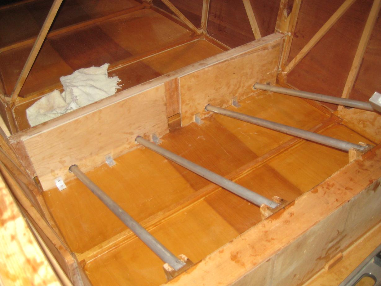
Above, you get the idea. The oak blocks in which the tubes are mounted are hidden, tucked up snugly to the underside of the rear spar. The seat support tubes are 3/4" diameter 6061-T6 aluminum with a wall thickness of .058 inches. When I place a piece of plywood on top of them and sit on it, it's rock solid. However, I would not feel comfortable with tubes of any thinner wall thickness.
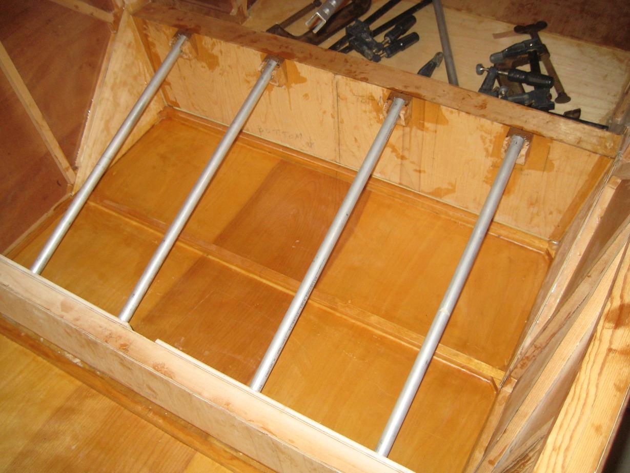
Above, you can see the other four oak blocks I epoxied to the front spar to serve as forward mounts for the seat support tubes. You can not see them in the picture, but there are 1/4" ledges beneath the metal tabs in which the tubes rest. To these ledges, I will flox industrial strength velcro strips. The tubes will also have velcro strips attached to them. So, the tubes will stick in place.
The slots in the forward mounting blocks are slightly undersized at the very top so that you have to pop the seat support tubes out to remove them. The tubes will not come out of their holes if the airplane--God forbid--goes inverted. The seat bottom will also be velcroed in place, further ensuring that the tubes will stay put.
Each aluminum tube weighs 4.5 ounces. So far, including the oak mounting blocks, I'm at 2 pounds, 2 ounces for my seat installation.
My seat itself will be made of 1/2" thick Last-a-foam covered with two layers of fiberglass on each side. The seat bottom will tilt back at a 20 degree angle. The seat back will sit at about 65 degrees up from horizontal--the same as on the Nvaero prefabricated fuselages. It might be wishful thinking, but I hope to keep the total weight of my seat installation at about 4.5 pounds, which would be in the same ballpark as the sling seat installation from the plans.
Ultimately, this configuration is light, easily removeable, and involves no extra holes in the spars.